CLOSE


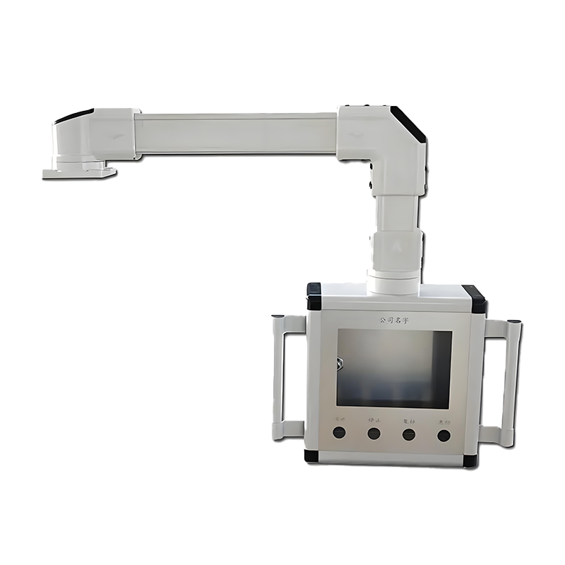
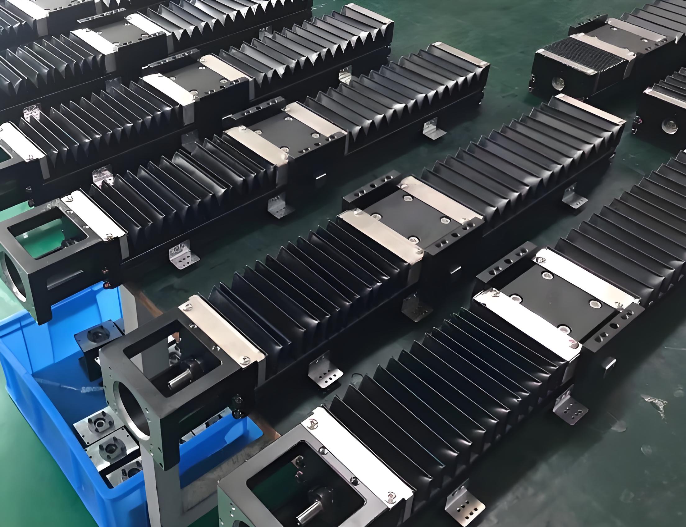
Machine tool cantilever operating parts
The cantilever operating parts of machine tools refer to the operating control components installed on the cantilever structure, which are usually used for the operation and control of machine tools or other automated equipment. The cantilever operating parts integrate various control devices, such as buttons, display screens, knobs, emergency stop switches, etc., which facilitate operators to control the operation of machine tools in a safe and convenient location.

Related products

Model Inquiry

Phone
+86 15369455556

info@cn-hckj.com

+86 15803375432
The main components of the machine tool cantilever operating part:
1. Display screen:
Usually an important part of the CNC Machine Tools, providing the HMI to display the machine tool status, operating instructions, program information, etc.
The display screen may be touch-sensitive or may be equipped with physical buttons for entering operating instructions.
2. Control buttons and knobs:
Start/Stop button: used to start or stop the operation of the machine tool.
Mode selection switch: can be used to select different working modes, such as manual, automatic or programming mode.
Adjustment knob: used to adjust processing parameters, such as feed speed, spindle speed, etc.
3. Emergency stop switch:
Used to immediately stop the machine tool operation in an emergency to ensure the safety of the operator and equipment.
Generally designed to be conspicuous red and easy to operate.
4. Keyboard or handwheel:
On some CNC machine tools, the cantilever operating part may be equipped with a keyboard for entering CNC programs or commands.
The handwheel can manually and accurately adjust the movement of the machine tool, such as feed operation or manual positioning.
5. USB interface or data interface:
Data interfaces are often set on cantilever operating parts to facilitate operators to import and export CNC programs or connect external devices (such as USB drives, network interfaces, etc.).
6. Signal indicator lights:
Show the operating status of the machine tool (for example, green indicates normal operation, red indicates fault or shutdown), so that operators can quickly understand the status of the equipment.
Features of machine tool cantilever operating parts:
1. Flexible movement:
The cantilever structure enables the operating parts to flexibly adjust their positions. Operators can move the operating table to a comfortable operating position as needed to improve work efficiency.
2. Space saving:
The cantilever design can separate the operating interface from the machine tool body to avoid occupying floor space, which is particularly suitable for environments with limited working areas.
3. Convenient operation:
All control functions are integrated on one operating platform, and operators can quickly complete the operation, debugging and maintenance of the machine tool.
4. Safe and reliable:
The operating parts are ergonomically designed and equipped with safety devices such as emergency stop and status indication to ensure the safety of machine tool operation.
Application scenarios:
Machine tool cantilever operating parts are widely used in various types of CNC machine tools, automation equipment and production lines, and are particularly suitable for processing occasions that require frequent operation or monitoring, such as:
CNC machining center: Operators can monitor and control the processing process in real time through cantilever operating parts.
Automated production line: Cantilever operating parts are used to control and adjust multiple equipment or processes on the production line.
In short, machine tool cantilever operating parts make operation more efficient and flexible by integrating control and display functions, and improve the overall controllability and safety of machine tools.
Product Packaging
Craftsmanship
Design Phase
Requirement Analysis: Determine the size, shape, and performance standards of the protective cover based on client needs or equipment requirements.
CAD Design: Use CAD software for detailed design of the protective cover, generating 2D or 3D drawings to ensure precise matching with the machine structure and operating trajectory.
Material Selection
Material Type: Choose materials based on different environmental requirements; common materials include **steel plates, stainless steel, aluminum alloy**, or special fabrics (like heat-resistant fibers, PVC) for flexible covers.
Thickness and Hardness: Select appropriate thickness and hardness based on machine operation strength and environment to ensure sufficient protection without affecting machine operation.
Material Processing
Cutting: Use **laser cutting**, **plasma cutting**, or **CNC shearing machines** to precisely cut steel plates or other materials according to design drawings.
Bending and Shaping: Employ **CNC bending machines** or other machinery for bending to form the required shapes like flat, arc, or cylindrical.
Welding and Assembly
Welding: For hard materials like steel plates, use **TIG welding** or **MIG welding** to join structural parts.
Riveting or Bolt Connection: In some cases, bolts or rivets are used for connections, especially in structures that need to be disassembled later.
Frame Installation: Some covers require internal frames for added strength and support, which will be assembled with the cover shell.
Surface Treatment
Polishing and Grinding: The surface after welding or processing usually requires polishing and grinding to remove burrs and slag, ensuring a smooth finish.
Corrosion Treatment: Depending on the environment, perform **plating**, **painting**, or **powder coating** to enhance corrosion resistance and wear resistance, especially for covers used in humid or corrosive conditions.
Heat Treatment: Some materials undergo **heat treatment** to increase strength and durability.
Quality Inspection
Dimensional Inspection: Precisely measure the dimensions of the protective cover to ensure perfect fit with the machine equipment.
Strength and Durability Testing: Test the load capacity, impact resistance, and wear resistance of the protective cover to ensure it does not deform or damage over long-term use.
Appearance Check: Ensure even surface treatment with no scratches or bubbles.
Installation and Debugging
Pre-assembly: Sometimes trial assembly is conducted in the workshop to ensure good matching of the protective cover's parts with the machine's interfaces and guides.
Installation Debugging: Install the protective cover on the machine and conduct actual operation debugging to ensure it does not interfere with the machine's motion trajectory and effectively protects key components.
Packaging and Shipping
Protection Processing: Finished protective covers are usually packaged to prevent damage during transport; rust-proof oil or protective film may be used as necessary.
Shipping and Installation Guidance: Deliver the finished product to the client's site and provide detailed installation instructions or technical support to ensure correct installation and use.
C
O
N
T
A
C
T
You can contact us through the contact information below, and we will arrange personnel communication in time after receiving your inquiry. You can also click the chat button in the lower right corner to communicate with us online in real time!